Saturday, June 6, 2015

Huawei - Switch: Basic QinQ Tunnel (aka 802.1Q Tunneling)

How to Configure Basic QinQ?

Posted on December 8, 2014


Networking Requirements

As shown in the below figure, there are two enterprises on the network, Enterprise 1 and Enterprise 2. Enterprise 1 has two office locations, and Enterprise 2 has 2 office locations. The office locations of the two enterprises access SwitchA and SwitchB of the ISP network. A non-Huawei device with the TPID value 0x9100 exists on the public network.

The requirements are as follows:

  • Enterprise 1 and Enterprise 2 plans their VLANs independently.
  • Traffic of the two branches is transparently transmitted on the public network. Users using the same services in the two branches are allowed to communicate and users using different services are isolated.

You can configure QinQ to meet the preceding requirements. VLAN 100 provided by the public network can be used to implement communication of Enterprise 1 in the two branches and VLAN 200 is used for Enterprise 2. You can set the TPID value in the outer VLAN on the interface that connects the non-Huawei device to implement communication between devices.

Note: This example can be applied to Huawei switches higher level than Quidway S2700 and with EI version.


Configuring basic QinQ

configuring-basic-qinq


Configuration Roadmap

The configuration roadmap is as follows:

  • Configure VLAN 100 and VLAN 200 on both SwitchA and SwitchB. Set the link type of the interface to QinQ and add the interfaces to VLAN. In this way, different outer VLAN tags are added to different services.
  • Add interfaces connecting to the public network on SwitchA and SwitchB to VLAN 100 and VLAN 200 to permit packets from these VLANs to pass through.
  • Set the TPID values in the outer VLAN tag on interfaces connecting to the public network on SwitchA and SwitchB to implement communication between the device with devices from other vendors.

Procedure


Create VLANs.

# Create VLAN 100 and VLAN 200 on SwitchA.
<HUAWEI> system-view
[HUAWEI] sysname SwitchA
[SwitchA] vlan batch 100 200

# Create VLAN 100 and VLAN 200 on SwitchB.
<HUAWEI> system-view
[HUAWEI] sysname SwitchB
[SwitchB] vlan batch 100 200


Set the link type of the interface to QinQ.

# Configure GE0/0/1 and GE0/0/2 of SwitchA as QinQ interfaces. Set the VLAN of GE0/0/1 to VLAN 100 and the VLAN of GE0/0/2 to VLAN 200. The configuration of SwitchB is similar to the configuration of SwitchA, and the configuration details are not mentioned here.
[SwitchA] interface gigabitethernet 0/0/1
[SwitchA-GigabitEthernet0/0/1] port link-type dot1q-tunnel
[SwitchA-GigabitEthernet0/0/1] port default vlan 100
[SwitchA-GigabitEthernet0/0/1] quit

[SwitchA] interface gigabitethernet 0/0/2
[SwitchA-GigabitEthernet0/0/2] port link-type dot1q-tunnel
[SwitchA-GigabitEthernet0/0/2] port default vlan 200
[SwitchA-GigabitEthernet0/0/2] quit

Configure the interface connecting to the public network on the switch.

# Add GE0/0/3 of SwitchA to VLAN 100 and VLAN 200. The configuration of SwitchB is similar to the configuration of SwitchA, and the configuration details are not mentioned here.
[SwitchA] interface gigabitethernet 0/0/3
[SwitchA-GigabitEthernet0/0/3] port link-type trunk
[SwitchA-GigabitEthernet0/0/3] port trunk allow-pass vlan 100 200
[SwitchA-GigabitEthernet0/0/3] quit

Configure the TPID value for an outer VLAN tag

# Set the TPID value of an outer VLAN tag to 0x9100 on SwitchA.
[SwitchA] interface gigabitethernet 0/0/3
[SwitchA-GigabitEthernet0/0/3] qinq protocol 9100

# Set the TPID value of an outer VLAN tag to 0x9100 on SwitchB.
[SwitchB] interface gigabitethernet 0/0/3
[SwitchB-GigabitEthernet0/0/3] qinq protocol 9100

Verify the configuration.

In Enterprise 1, ping a PC of a VLAN in a branch from a PC of the same VLAN in another branch. If the two PCs can ping each other, internal users of Enterprise 1 can communicate.

In Enterprise 2, ping a PC of a VLAN in a branch from a PC of the same VLAN in another branch. If the two PCs can ping each other, internal users of Enterprise 2 can communicate.

Ping a PC in a VLAN of Enterprise 2 in a branch from a PC in the same VLAN of Enterprise 1 in either branch. If the two PCs cannot ping each other, users in Enterprise 1 and Enterprise 2 are isolated.


Configuration Files

# Configuration file of SwitchA
sysname SwitchA
#
vlan batch 100 200
#
interface GigabitEthernet0/0/1
port link-type dot1q-tunnel
port default vlan 100
#
interface GigabitEthernet0/0/2
port link-type dot1q-tunnel
port default vlan 200
#
interface GigabitEthernet0/0/3
qinq protocol 9100
port link-type trunk
port trunk allow-pass vlan 100 200
#
return


#Configuration file of SwitchB
sysname SwitchB
#
vlan batch 100 200
#
interface GigabitEthernet0/0/1
port link-type dot1q-tunnel
port default vlan 100
#
interface GigabitEthernet0/0/2
port link-type dot1q-tunnel
port default vlan 200
#
interface GigabitEthernet0/0/3
qinq protocol 9100
port link-type trunk
port trunk allow-pass vlan 100 200
#
return

The more information about technical support you can consult with our engineer – Bill, and his e-mail address is as below:

bill@huanetwork.com

Taken From: http://www.huanetwork.com/blog/how-to-configure-basic-qinq/

Huawei - Router: Traffic Shapping

How to Configure Traffic Shaping for Huawei AR Routers?

Applicability

This example applies to all versions and Huawei AR routers.


Networking Requirements

As shown in the below figure, the LAN of an enterprise connects to Eth2/0/0 of RouterA through Switch. RouterA connects to the WAN through GE3/0/0. The voice, video, and data services are deployed on the LAN.

Packets of different services are identified by 802.1p priorities on the LAN. RouterA sends service packets to queues based on 802.1p priorities. When packets reach the WAN through GE3/0/0, jitter may occur. To prevent jitter and ensure bandwidth for services, perform the following configuration:

  • Set the CIR on each interface to 8000 kbit/s.
  • Set the CIR for voice service packets to 256 kbit/s and the CBS to 6400 bytes.
  • Set the CIR for video service packets to 4000 kbit/s and the CBS to 100000 bytes.
  • Set the CIR for data service packets to 2000 kbit/s and the CBS to 50000 bytes.


clip_image001

Traffic shaping networking diagram

Procedure

Configure RouterA.

sysname RouterA
#
vlan batch 10

# Create a queue profile qp1.
qos queue-profile qp1

# Set the CIR for queue 2 to 2000 kbit/s and the CBS to 50000 bytes.                
queue 2 gts cir 2000 cbs 50000

# Set the CIR for queue 5 to 4000 kbit/s and the CBS to 100000 bytes.
queue 5 gts cir 4000 cbs 100000

# Set the CIR for queue 6 to 256 kbit/s and the CBS to 6400 bytes.
queue 6 gts cir 256 cbs 6400

# Set the scheduling mode to queues 0 to 5 to weighted fair
# queuing (WFQ), and set the scheduling mode for queue 6 and
# queue 7 to priority queuing (PQ).

schedule wfq 0 to 5 pq 6 to 7


interface Vlanif10
ip address 192.168.1.1 255.255.255.0


interface Ethernet2/0/0
# Set the link type of the interface to trunk.
port link-type trunk
 
# Add the trunk interface to VLAN 10.
port trunk allow-pass vlan 10
 
# Trust 802.1p priorities of packets on the interface.
trust 8021p


interface GigabitEthernet3/0/0
ip address 192.168.4.1 255.255.255.0 

# Apply the queue profile qp1 to the interface.
qos queue-profile qp1 

# Set CIR for the interface to 8000 kbit/s and the CBS to 200000 bytes.
qos gts cir 8000 cbs 200000  

Verify the configuration

Run the display qos queue statistics interface gigabitethernet 3/0/0 command on RouterA to check packet statistics in queues on GE3/0/0. You can see that the output rate of each queue is within the configured limit. When a queue is full, excess packets are discarded.


Configuration Notes

Configure the interface of the switch connected to RouterA as a trunk interface and add the interface to service VLANs.

Configure RouterB to ensure that it can communicate with RouterA.

The traffic shaping CIR value configured on an interface must be larger than or equal to the sum of CIR values of all queues on the interface. Otherwise, packets in high-priority queues may fail to be scheduled.

The more information about technical support you can consult with our engineer – Bill, and his e-mail address is as below:

bill@huanetwork.com

Taken From: http://www.huanetwork.com/blog/how-to-configure-traffic-shaping-for-huawei-ar-routers/

Huawei - Switch: Voice Vlan and LLDP Config

How to Configure LLDP on Huawei Switch to Provide VoIP Access?
Posted on December 16, 2014

Networking Requirements

Flows of the HSI, VoIP, and IPTV services are transmitted on the network. Users require high quality of the VoIP service. Therefore, voice data flows must be transmitted with a high priority. If a voice device supports LLDP and has a high 802.1p priority (for example, 5), you can configure LLDP and Voice VLAN on the switch. Then the switch uses the LLDP protocol to deliver the Voice VLAN ID to the voice device and does not change the packet priority.

As shown in the below figure, after a Voice VLAN is configured on the Switch, the voice device learns the Voice VLAN ID using LLDP.


Configuring LLDP to provide VoIP access


clip_image001

Note: It can be applied to all Huawei Switches, like Huawei S2700, Huawei S3700 switches and Quidway S5700, etc.


Configuration Roadmap

The configuration roadmap is as follows:

  • Create VLANs.
  • Configure the link type and default VLAN of the interface connected to the IP phone.
  • Enable the Voice VLAN function on the interface.
  • Configure the interface to join the Voice VLAN in manual mode.
  • Set the working mode of the Voice VLAN.
  • Configure the interface to trust the 802.1p priority of packets.
  • Enable LLDP globally and on the interface.


Procedure

Configure VLANs and interface on the Switch.

# Create VLAN 2 and VLAN 6.
<HUAWEI> system-view
[HUAWEI] vlan batch 2 6

# Configure the link type and default VLAN of GigabitEthernet0/0/1.
[HUAWEI] interface gigabitethernet 0/0/1
[HUAWEI-GigabitEthernet0/0/1] port hybrid pvid vlan 6
[HUAWEI-GigabitEthernet0/0/1] port hybrid untagged vlan 6

Configure the Voice VLAN on the Switch.

# Enable the Voice VLAN on GigabitEthernet0/0/1.
[HUAWEI-GigabitEthernet0/0/1] voice-vlan 2 enable

# Configure the mode in which GigabitEthernet0/0/1 is added to the Voice VLAN.
[HUAWEI-GigabitEthernet0/0/1] voice-vlan mode manual
[HUAWEI-GigabitEthernet0/0/1] port hybrid tagged vlan 2

# Configure the working mode of the Voice VLAN.
[HUAWEI-GigabitEthernet0/0/1] undo voice-vlan security enable

#Configure the interface to trust the 802.1p priority of packets.
[HUAWEI-GigabitEthernet0/0/1] trust 8021p (inner)
[HUAWEI-GigabitEthernet0/0/1] quit

NOTE: The format of the trust 8021p (inner) command varies depending on the device model.


Enable LLDP

[HUAWEI] lldp enable
[HUAWEI] interface gigabitethernet 0/0/1
[HUAWEI-GigabitEthernet0/0/1] lldp enable
[HUAWEI-GigabitEthernet0/0/1] return


Verify the configuration.

Run the display voice-vlan 2 status command to check the Voice VLAN configuration, including the mode in which the interface is added to the Voice VLAN, working mode, and aging time of the Voice VLAN.

<HUAWEI> display voice-vlan 2 status
Voice VLAN Configurations:
—————————————————
Voice VLAN ID           : 2
Voice VLAN status       : Enable
Voice VLAN aging time   : –
Voice VLAN 8021p remark : 6
Voice VLAN dscp remark   : 46
———————————————————-
Port Information:
———————————————————–
Port                     Add-Mode Security-Mode Legacy   PribyVLAN Untag
——————————————————————————-
GigabitEthernet0/0/1     Manual     Normal         Disable Enable     Disable

Configuration File

#Configuration file of the Switch

vlan batch 2 6
#                                   
lldp enable                       
#                                 
interface GigabitEthernet0/0/1     
voice-vlan 2 enable               
port hybrid pvid vlan 6           
port hybrid tagged vlan 2
port hybrid untagged vlan 6
trust 8021p (inner)
#
return

The more information about technical support you can consult with our engineer – Bill, and his e-mail address is as below:

bill@huanetwork.com

Taken From: http://www.huanetwork.com/blog/how-to-configure-lldp-on-huawei-switch-to-provide-voip-access/

Huawei - Switch: Local Port Mirroring (aka SPAN)

How to Configure Local Port Mirroring?

As shown in Figure 1, HostA is connected to GigabitEthernet0/0/1 on SwitchA, and Server is directly connected to GigabitEthernet0/0/2 on SwitchA.

Users want to use the monitoring device (Server) to monitor packets sent from HostA.

networking-diagram-of-local-port-mirroring

Figure 1 Networking diagram of local port mirroring

Note: e example can be applied to Huawei Switches (like Huawei S2700, Huawei S3700 switches and Quidway S5700, etc )


Configuration Roadmap

The configuration roadmap is as follows:

  1. Configure GigabitEthernet0/0/2 on SwitchA as the local observing port so that Server can receive mirrored packets.
  2. Configure GigabitEthernet0/0/1 on SwitchA as the mirrored port to monitor packets passing through the mirrored port.

Procedure

  1. Configure an observing port.

# Configure GigabitEthernet0/0/2 on SwitchA as the local observing port.

<HUAWEI> system-view
[HUAWEI] sysname SwitchA
[SwitchA] observe-port 1 interface gigabitethernet 0/0/2

  1. Configure a mirrored port.

# Configure GigabitEthernet0/0/1 on SwitchA as the mirrored port to monitor packets sent from HostA.

[SwitchA] interface gigabitethernet 0/0/1
[SwitchA-GigabitEthernet0/0/1] port-mirroring to observe-port 1 inbound
[SwitchA-GigabitEthernet0/0/1] return

  1. Verify the configurations.

# Check the observing port configuration.

<SwitchA> display observe-port

———————————————————————-
Index         : 1
Untag-packet   : No
Interface     : GigabitEthernet0/0/2
———————————————————————-


# Check the mirrored port configuration.

<SwitchA> display port-mirroring
———————————————————————-
Observe-port 1 : GigabitEthernet0/0/2
———————————————————————-
Port-mirror:
———————————————————————-
Mirror-port               Direction Observe-port
———————————————————————-
1   GigabitEthernet0/0/1     Inbound   Observe-port 1
———————————————————————-


Configuration File

# Configuration file of SwitchA

sysname SwitchA
#
observe-port 1 interface GigabitEthernet0/0/2
#
interface GigabitEthernet0/0/1
port-mirroring to observe-port 1 inbound
#
return

The more information about technical support you can consult with our engineer the e-mail address is as below:

support@huanetwork.com

Taken From: http://www.huanetwork.com/blog/how-to-configure-local-port-mirroring/

Huawei - Router: Password Recovery - BootROM (aka ROMmon)

How do I Log into the Device Using BootROM If I Forget the Console Login Password?
The console interface on RouterA connects to the PC and the console login password is forgotten. It is required that BootROM (aka ROMmon) be used to log in to the device. This example applies to V200R003C00 and later versions, and all Huawei AR routers.

clip_image001Figure 1 - Networking for login through BootROM when the console login password is forgotten

Log in to the router through the console port.

NOTE: When performing operations, ensure that users on the serial port are kept online.
Restart RouterA. Press Ctrl+B to enter the BootROM menu when the following information is displayed:

BIOS Creation Date : Nov 10 2011, 14:41:12                                   
DDR DRAM init : OK                                                           
Start Memory Test ? (‘t’ or ‘T’ is test):skip                                 
Copying Data : Done                                                           
Uncompressing : Done                                                           
USB2 Host Stack Initialized.                                                 
USB Hub Driver Initialized                                                   
USBD Wind River Systems, Inc. 562 Initialized                               
Octeon Host Controller Initialize……Done.                                 

Press Ctrl+B to break auto startup … 3   

After pressing Ctrl+B, you need to enter the password

  • Versions earlier than V200R005C00: huawei,
  • V200R005C00 and later versions: Admin@huawei

to enter the BootROM menu.


In general the default user and password are:

in new equipments or with a updated image the password is “Password2”.


Select choice 7 to enter the Password Manager menu.

Main Menu 
1. Default Startup                                                         
2. Serial Menu                                                           
3. Network Menu                                                           
4. Startup Select                                                         
5. File Manager                                                           
6. Reboot                                                                 
7. Password Manager

Enter your choice(1-6):7                                                     
Select choice 2 to delete the console login password.

PassWord Menu                                                         
1. Modify the menu password                                               
2. Clear the console login password                                       
3. Return                                                                 
Enter your choice(0-1):2

Clear the console login password Succeed!

PassWord Menu                                                         
1. Modify the menu password                                               
2. Clear the console login password                                       
3. Return
           
Enter your choice(0-1):0
Select 1 and wait for a while. Then you can log in to the device.

Main Menu                                                             
1. Default Startup                                                         
2. Serial Menu                                                           
3. Network Menu                                                           
4. Startup Select                                                         
5. File Manager                                                           
6. Reboot                                                                 
7. Password Manager

Enter your choice(1-6):1

The more information about technical support you can consult with our engineer the e-mail address is as below:

support@huanetwork.com


Taken From: http://www.huanetwork.com/blog/how-do-i-log-into-the-device-using-bootrom-if-i-forget-the-console-login-password/

Saturday, May 9, 2015

Windows 8 and The New UEFI BIOS

How To Access The BIOS On A Windows 8 Computer

clip_image001

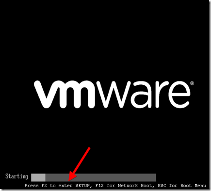
Among the many changes coming with Windows 8 and new computers designed for it is a change in the way we access our computers’ BIOS. No longer do we press a certain key during the boot process to reveal the BIOS – instead, an option to access the BIOS is located in Windows 8’s boot options menu.

Traditionally, computers displayed a message like “Press F2 to enter setup” at the beginning of the boot process. Pressing this key entered the computer’s BIOS. However, Windows 8 hardware uses the UEFI replacement for the traditional BIOS, like Macs do. Some solid-state drive-equipped Windows 8 PCs boot so fast that you’d only have a 200 millisecond (that’s 0.2 seconds) window of opportunity to press the key combination.


Windows 8 Hardware vs. Old Computers With Windows 8

Note that this new method only applies if you purchased a new computer with Windows 8 preinstalled – these will use UEFI. However, if you’ve installed Windows 8 on an existing computer that uses the legacy BIOS system, you’ll access the BIOS in the same way as always by pressing the key that appears during your boot process.

This key is often F2 or Delete, but it can also be other keys. The exact key depends on your computer – if you don’t see the appropriate key displayed on your screen during the boot-up process, consult your computer’s manual.

clip_image002


Accessing Boot Options

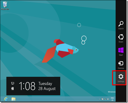
There are several ways to access Windows 8’s boot options menu. The easiest one to find is in the PC Settings application – press WinKey+C to reveal the Charms bar, click Settings, and select Change PC settings to access it.

clip_image003

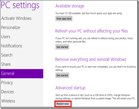
In the PC Settings application, select the General category and click the Restart now button under Advanced startup. Your computer will restart and you’ll enter the Windows 8s boot options menu, where you can access the UEFI BIOS and change other settings.

clip_image004

In more updated versions of windows 8 (like 8.1), the Advanced startup has moved:

Windows Key+C > Settings > Change PC settings > Update and recovery > Recovery > Advanced startup + Restart now

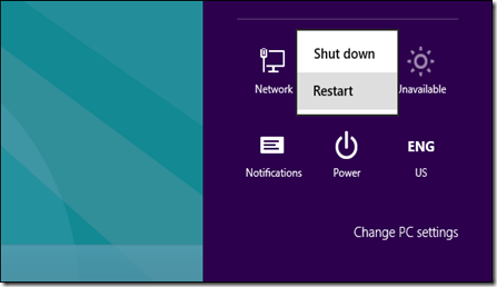
You can also hold Shift while clicking Restart in the Shut Down menu to restart your computer into the boot options menu. This is a quick way to restart into the boot options menu, as you can access the Shut Down button from the Charms anywhere on your system.

clip_image005

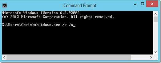
Command-line geeks will be happy to know they can run a special shutdown.exe command in a Command Prompt window to restart their computer directly into the boot options menu:

Shutdown.exe /r /o

clip_image006


Accessing UEFI BIOS

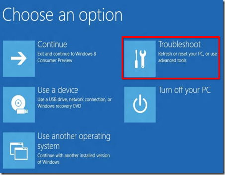
The boot options menu has been designed to integrate some commonly used options that people went into the BIOS for. For example, if you want to boot your computer off a USB drive, DVD or CD, or another device, you can click the Use a device tile in the boot options menu and select the device you want to boot from.

If you’re just here to access your computer’s UEFI BIOS, click the Troubleshoot tile.

clip_image007

This will reveal an Advanced Options screen with a variety of tools – the UEFI Firmware Settings tile will take you to your computer’s BIOS. (On UEFI, which stands for “Unified Extensible Firmware Interface”, the firmware settings menu is equivalent to a traditional PC’s BIOS.)

clip_image008

If you don’t see the UEFI Firmware Settings tile here, your computer doesn’t use UEFI. You’ll need to access the BIOS in the traditional way, by pressing a specific key during the boot-up process. See the first section above for more information.

If there’s an error booting Windows, you won’t be locked out of the BIOS — the boot options screen will appear when you start your computer. From here, you can repair Windows or enter your BIOS.


Why the Change?

While this may be slightly inconvenient, as there’s no way to access the BIOS in normal use without booting into Windows first, it’s surely necessary. Microsoft’s blog post about this on the Building Windows 8 blog describes how this new system came to be. With the increased boot speed, some systems had a less than 200 millisecond window of opportunity to press a key. Even the best key-tappers at Microsoft could only press a key once every 250ms — to access the BIOS, frantic tapping, luck, and several compuer reboots were all necessary.

This also brings some much-needed consistency to Windows 8 computers — they’ll all have a consistent way of accessing the BIOS. Currently, different computers use different keys at start-up.

While Windows 8 may have some questionable design decisions that some people will dislike, this shouldn’t be one of them. The new method of accessing the BIOS is necessary and well-implemented.

Taken From: http://www.makeuseof.com/tag/how-to-access-the-bios-on-a-windows-8-computer/ (By Chris Hoffman)

Tuesday, May 5, 2015

Cisco / Linux - Decapsulating Cisco ERSPAN With Linux

Decapsulation ERSPAN Traffic With Open Source Tools

Posted on May 3, 2015 by Radovan Brezula

Cisco Encapsulated Remote SPAN (ERSPAN) feature allows to monitor traffic on one or more ports and send the monitored traffic to one or more destination ports.  Traffic is encapsulated into GRE tunnel and routed via network to ERSPAN destination. Any device that supports ERSPAN can be used as ERSPAN destination. It might be another Cisco device or Linux with installed software that can decapsulate GRE traffic.

The goal of this article is to show methods and tools for decapsulation of  ERSPAN traffic. For this purpose I have built simple lab that consists of a Cisco CSR 1000v router and two Linux boxes. Core Linux represents a network host and generates network traffic (ICMP) that is going to be monitored. It is connected to the port GigabitEthernet1 of the Cisco router. The router is configured to monitor traffic on the port Gi1 and it sends traffic encapsulated in GRE tunneling protocol to IP address 10.230.10.1. It is the IP address of the ERSPAN destination configured on Linux  Security Union. Security Onion is a unique Linux distro for intrusion detection, network security monitoring, and log management based on Ubuntu however any other Linux distro can be used.

clip_image001

Picture 1 - ERSPAN Lab Topology

Below is an example of ERSPAN configuration on the CSR 1000v router. This is the source ERSPAN type and with configured rspan_id 1. The interface Gi1 is being monitored and the GRE traffic is sent to ERSPAN destination address IP 10.230.10.1.

CSR1000v# show running-config | b monitor
monitor session 1 type erspan-source
description ERSPAN to 10.230.10.1
source interface Gi1
destination
erspan-id 1
mtu 1464
ip address 10.230.10.1
origin ip address 10.230.10.2

Capturing ERSPAN Traffic with Wireshark

We are going to capture and analyze ERSPAN traffic with Wireshark packet sniffer. First configure IP address 10.230.10.1 on interface eth1 of the Linux Security Onion.

janosik@onion:~$ sudo su
root@onion# ip address add 10.230.10.1/24 dev eth1

Now use Wireshark to capture GRE traffic on Security Onion on its interface eth1 and ping the router IP address 192.168.1.2 from the Linux Core host (IP 192.168.1.1). If the source ERSPAN is properly configured on router, packets from the subnet 192.168.1.0/24 should appear in Wireshark output.

A closer look at the picture below reveals that the original packet ICMP packet (MAC header, IPv4 header and ICMP header) is now encapsulated as following.

MAC header + IPv4 header (10.230.10.2, 10.230.10.1) + GRE header (Protocol type ERSPAN) + ERPAN header + (original packet)

clip_image002

Picture 2 - Encapsulated GRE Traffic Captured on Interface Eth1

An original ICMP packet is encapsulated into GRE tunnel and the new outer MAC and IPv4 + GRE + ERSPAN headers are added to original packets. It allows encapsulated traffic to be forwarded through network to ERSPAN destination. However if we want software application such as IPS/IDS to analyze encapsulated packets, the outer L2 and L3 headers must be striped from packet. This can be done with tools such as RCDCAP  which dissects packets from GRE tunnel.


Configuring GRE tunnel on ERSPAN Destination Device

If for some reason we do not want to install special software that dissects packets from GRE tunnel we can configure GRE tunnel on ERSPAN destination (Linux Security Onion) and let IDS to listen on a tunneled interface. Thanks to this configuration the outer MAC and IPv4 headers are stripped and do no appear in Wireshark output.

a) Load gre module to kernel

janosik@onion:~$ sudo su
root@onion# modprobe ip_gre

b) Choose receiving interface and assign IPv4 to it

root@onion# ip addr add 10.230.10.1/24 dev eth1

Set the MTU of the network interface that receives GRE packets larger than 1500 e.g. to 1900.  Otherwise we are going to miss some bytes in larger packets.

root@onion# ip link set dev eth1 mtu 1900

c) Create virtual tunnel interface and associate it with IP previously configured on eth1 interface

root@onion# ip tunnel add mon0 mode gre local 10.230.10.1 ttl 8

d) Add IP address to interface mon0 which is not used for anything

root@onion# ip addr add 1.1.1.1/30 dev mon0

e) Change the state of mon0 device to up

root@onion# ip link set mon0 up

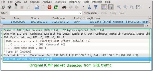
Again, generate some traffic in the subnet 192.168.1.0/24 and configure Wireshark to listen on interface mon0. Notice that the outer MAC and Ipv4 header are now stripped from the ICMP packet.

clip_image003

Picture 3 - Decapsulated Traffic Captured on Interface Eth1

Using RCDCAP for Decapsulating ERSPAN Traffic

RCDCAP is wrapper program that dissects the traffic and creates a virtual interface where the traffic is already decapsulated. I've compiled it from the source and created the Ubuntu package RCDCap-0.7.99-Linux for Ubuntu 15.04. Be aware that additional packages are needed to get it working.

janosik@onion:~$ sudo su
root@onion# apt-get install libboost-regex1.55.0

Use apt-get to install the packages below. If they are not available in a repository  download them from here and install manually with dpkg -i command.

  • libboost-program-options1.48.0_1.48.0-3_amd64.deb
  • libboost-thread1.48.0_1.48.0-3_amd64.deb
  • libboost-system1.48.0_1.48.0-3_amd64.deb

root@onion# dpkg -i libboost-program-options1.48.0_1.48.0-3_amd64.deb libboost-thread1.48.0_1.48.0-3_amd64.deb libboost-system1.48.0_1.48.0-3_amd64.deb

Now we can install RCDCAP with the command.

root@onion# dpkg -i RCDCap-0.7.99-Linux.deb

Once RCDCAP is installed configure interface eth1 to prepare for capturing.

janosik@onion:~$ sudo su
root@onion# ip addr add dev eth1 10.230.10.1/24
root@onion# ip link set dev eth1 mtu 1900
root@onion# ip link set dev eth1 up

Start RCDCAP with the command below and let Wireshark to listen on interface mon1.

root@onion# rcdcap -i eth1 --erspan --tap-persist --tap-device mon1 --expression "host 10.230.10.1"

We can see that RCDCAP have dissected monitored traffic from GRE and only original MAC + IPv4 + ICMP headers and pyaload are presented in Wireshark output.

clip_image004

Picture 4 - Decapsulated Traffic Captured on Interface Mon1

Reference:

Taken From: http://brezular.com/2015/05/03/decapsulation-erspan-traffic-with-open-source-tools/