Sunday, January 26, 2014

Share Your Internet via Wifi – Windows 8 (Tablet / Desktop)

How to Share Your 3G/4G Internet Connection With Other Devices From Your Windows Tablet

clip_image001

I’m sure that we are not the only people who carry around multiple devices and only have 1 or 2 mobile data plans. If the device carrying your data plan happens to be your Windows tablet, start celebrating. We’ll show you how you can share that data goodness with your other devices.

Note: The following method was tested and confirmed working on a Samsung ATIV Tab.

How to Share Your Internet Connection With Other Devices From Your Windows Tablet

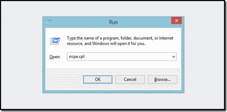
Press the Windows + R key combination to bring up a run box, type ncpa.cpl and hit enter.

clip_image003

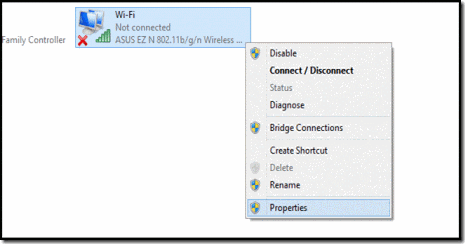
When your network connections control panel window opens, right-click on your Wireless network adapter and select properties from the context menu.

clip_image005

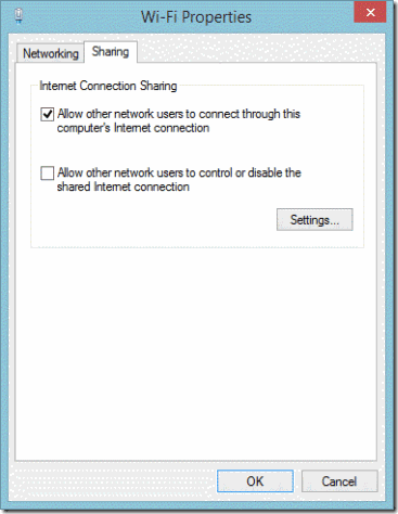
Now switch over to the Sharing tab and allow other devices to use your machine’s internet by selecting the first checkbox and then unchecking the second before clicking on the OK button.

clip_image007

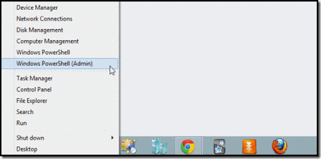
Now press the Win + X keyboard combination to bring up the WinX menu in the bottom left of your screen. From here you will need to launch an administrative command prompt, or PowerShell prompt if you happen to be running Windows 8.1.

clip_image009

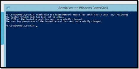
The first thing we need to do is set up the wireless network, which is done using the netsh command like so:

netsh wlan set hostednetwork mode=allow ssid=”How-To Geek” key=”Pa$$w0rd$”

Where ssid is the name of your network and key is the password you want users to connect with. It is also worth mentioning that the access point is created with WPA2-PSK (AES) encryption.

clip_image011

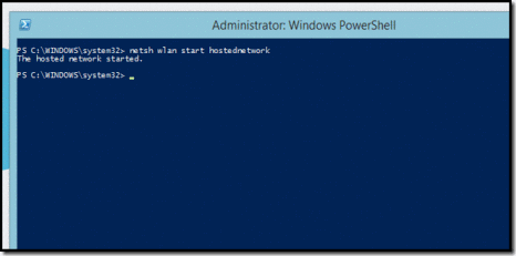
Finally we need to start broadcasting our newly created network so that our other devices can pick it up.

netsh wlan start hostednetwork

clip_image013

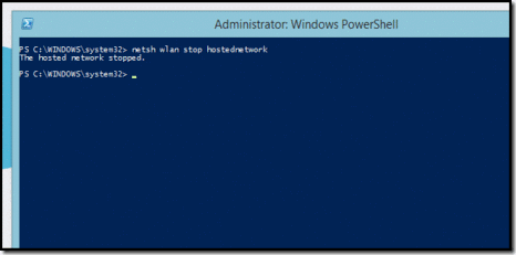
That’s all there is to it. When you are done, you can simply run the following command to stop the network.

netsh wlan stop hostednetwork

clip_image015

Taken From: http://www.howtogeek.com/167504/how-to-share-your-3g4g-internet-connection-with-other-devices-from-your-windows-tablet/

Friday, January 24, 2014

Be a Mechanic - With Android and Linux

"Check Engine Soon"—that little orange light on your car's instrument panel is possibly one of the more annoying things about modern automobiles. Ever had it pop on during a trip and wonder whether it was just something mundane, like your gas cap being loose, or whether it's something deathly serious and a piston could come shooting out the side of your engine block at any time? Well, thanks to an inexpensive little piece of hardware and an Android tablet, I'll help you decode that little orange light in your car.

The human race has had automobiles for more than 100 years now, but we've had computer monitors and control engine operation only for around 30 years or so. The first computer controls were primitive, hard to work with and expensive. Each automotive manufacturer had its own computer systems, protocols, connectors and trouble-code definitions. I worked as a mechanic during the late 1980s and early 1990s, and I remember those systems well—not fondly, of course, but well. Some of those systems required you to do crazy things like jump a connector with a piece of wire, then turn the key on and off three times and observe the Check Engine light as it flashed on and off. You'd have to count the number of flashes accurately and then look up the "trouble code" that flashed in a service manual, and you might get a clue as to what was wrong with the vehicle. Those early diagnostic systems made seasoned mechanics who were used to troubleshooting the machinery of an engine rather than its electronics shudder with trepidation. Over time, the manufacturers made the systems better. The Society of Automotive Engineers made the connector, protocol and trouble codes a standard in 1996, and with that, we've got the system in place today: OBD-II (Onboard Diagnostics, 2nd revision).

OBD-II Basics

Any car sold in the United States after 1996 uses the OBD-II computer system, so the majority of cars on the road today have this system. Thanks to OBD-II's standardization and age, lots of tools have been released to work with the system. Because OBD-II defines the connector and protocol, that means you need both a hardware device to interface with the connector and some software to speak the protocol.
The hardware I use is the Soliport ELM327 Bluetooth OBD-II Scanner (see the Amazon link in the Resources section of this article). It's a very inexpensive (less than $20) dongle that plugs in to the OBD-II port under your dashboard, draws its power directly from the car and converts the OBD-II-specific signals to serial-over-Bluetooth. There are other OBD-II scan tools on the market. Some are just plain-old cables to hook straight into a computer's RS-232 serial port, and others are as fancy as full-on bridges to a Wi-Fi network. And, there are other manufacturers of Bluetooth OBD-II scan tools, but just make sure whatever you get is based on the ELM327 chipset.

Another piece of hardware you'll need is a computer of some kind. Any Linux-powered laptop with Bluetooth will suffice, but the form factor is kind of clunky when you're dealing with a cramped automotive cockpit. (See the Using a Laptop to Scan Your OBD-II System sidebar if you want to use a laptop.) My personal preference is to use an Android device to interpret the signals coming from the OBD-II system in the car. I use a Nexus 7 tablet for this, but any Android device should work. I've used a Motorola Droid RAZR and the very first HTC G1 Android phone for this as well.

clip_image001
Figure 1. Tools of the Trade: a Nexus 7 Tablet and a Soliport Bluetooth OBD-II Scanner

Software-wise, my choice for this on Android is Torque, an excellent app that not only can collect all the OBD-II stats, but also graph and log them in myriad ways. (There's also a free version, Torque Lite, that has a fair deal of the functionality of the full version.) Grab either one from the Google Play store.
Note that this solution is for read-only access to the OBD-II system in the car. You can't modify the running parameters of the vehicle with this adapter, unfortunately (or fortunately, perhaps, as it's very easy to make a mess of things). Flashing your car's computer with a new fuel curve or ignition timing map is a nontrivial exercise that requires an adapter with different voltage levels and different software. So, don't worry about breaking your car with this solution—you're just "peeking under the hood".

Using a Laptop to Scan Your OBD-II System

Although it's possible to use a laptop to do the same duty as an Android device, it's a little more involved, as the Bluetooth protocol stack on a Linux laptop requires some more massaging than simply pairing up an Android device. However, if you're comfortable with the command line and Bluetooth commands like rfcomm, it's absolutely possible, and there are some good OBD-II packages like pyobd and openobd. You won't get some of Torque's value-add features, like accelerometer and GPS integration, but you still can use the laptop for diagnostic purposes and data logging.

Using an Old Nokia Internet Tablet to Scan Your OBD-II System

In the December 2008 issue of LJ, I wrote an article called "Hacking the Nokia Internet Tablet", and I talked about ways to hack and extend the Nokia N800 tablet. It turns out there's an application for the N800 and N810 called Carman that was designed to work with wired OBD-II adapters, but it works just fine with the Soliport Bluetooth Scanner. Carman used to be in the Maemo repositories. I no longer have a working N800, so I can't check that now, but when my N800 did work, I used it a few times to diagnose the car. So, if you've got a Nokia device sitting in a drawer gathering dust, pull it out and put it to use!

Using Torque and the Soliport Bluetooth Adapter

The Soliport adapter comes with a little CD-ROM in the box, but it's not required for use with an Android device. To get started, you first need to find the OBD-II port in your car. In most cars sold in the United States, the port is under the dash on the driver's side of the car. Find the port, and plug the Soliport in to it.
Next, start the car, because the OBD-II port isn't powered until the car's ignition is on. (Make sure your garage door is open, please. I don't want to receive hate mail from your relatives on how you suffocated from carbon monoxide poisoning!) Next, you need to go through the standard Bluetooth pairing process to pair your Android device to the Soliport adapter. (The pairing code is 1234 if you can't find it in the instructions—coincidentally, it's the same combination that's on my luggage.)
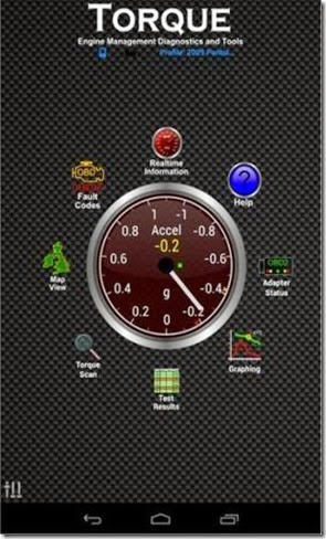
Once you've got your Android device all paired up to the Soliport, you're ready to fire up Torque. Start Torque on your Android device, and you'll be greeted with the Torque main screen.

clip_image002Figure 2. The Torque Home Screen

Setting Up Torque

Now that you have Torque up, select the little "settings" slider on the bottom left of the screen, and select "OBD2 Adapter Settings". Set the connection type as Bluetooth, and choose the Soliport if prompted. Go back to the main settings screen and select your desired units (Imperial or Metric), and any other preferences you choose, then flip back to the Torque main screen.

Next, you're going to create a "profile" for your vehicle. Select the settings slider from the main screen as before, then select "Vehicle Profile" and "Create new profile". Then, fill in the pertinent information about your vehicle. This information is used by Torque to compute things that can be calculated, like horsepower, fuel economy and other metrics. When you're done, go back to the main screen.

Checking for Fault Codes

Let's start by doing basic diagnostics on your car. From the main screen, select Fault Codes, then press the large magnifying glass to start a scan of your car's computer for trouble codes. If your Check Engine light is on, you'll probably find your issue represented as a code here. My father's 2001 Chevy Silverado pickup was showing a Check Engine light, and I ran a quick scan on it with Torque. It resulted in a trouble code of P1416. A quick Google search of that trouble code showed that it was the Secondary Air Valve, Bank 2. It turned out that was a little smog system valve right on top of the engine, on the passenger side. Amazon.com had that particular part for $37, and we had it at his house in two days.

I had the Check Engine light on my wife's Durango pop on not long after, and I used the tool to scan her car. Her car came back with a P0440 code, which means "Evaporative Emission Control System Malfunction". I searched a bit more on the Internet and found that the most common cause of this code is a broken or mis-installed fuel filler cap. It turned out that was exactly the case—her fuel filler cap wasn't tightened all the way. I tightened the cap and cleared the code via the Torque app, and it never returned.

Getting Performance Data

Those two cases listed above more than paid for the cost of the Soliport adapter and the Torque application, but Torque can do so much more. Torque can pull data from sources other than your OBD-II sensors. It also can poll your Android device's accelerometer and GPS. This means it can do performance calculations, such as 0–60 mph time (or 0–100 kph time), 1/4 mile time or even horsepower calculations. This requires that you get your car's data entered correctly into the vehicle profile during setup time, particularly the vehicle weight (including your weight as driver, and any other stuff you may have inside the car). If you do performance testing, make sure you're doing it safely—and don't violate any laws in your locality.

However, I think one of the coolest things that Torque and the Soliport adapter can do is they can act as an auxiliary instrument panel for your car. Any bit of information that passes through the OBD-II sensors can be logged, graphed or placed on a digital dial. You can pick and choose how you want that information presented as well—including the size and position of the graphs and dials. This information can be extremely valuable, for instance, displaying the current engine manifold vacuum. As a general rule, under cruise conditions, higher manifold vacuum means higher fuel economy, so having this gauge up can be handy on long trips.
clip_image003
Figure 3. Torque's Virtual Instrument Panel

Torque also has other features, like the ability to log your data for future analysis. It also can graph that data and correlate it to your GPS position and accelerometer data. This can be useful if you happen to be an amateur racer and would like to get information about your car's performance at certain points on the racetrack. Most people won't need that ability, but it's nice to know that the developer of Torque thought that out. All the data necessary to do those calculations is there, it just needs to be glued together.

Closing

Computer control systems in cars used to be mysterious, overly complicated, finicky pieces of technological voodoo to even the most seasoned mechanic. Scan tools were proprietary and cost thousands of dollars, and mechanics needed a special tool for each car manufacturer. With the advent of OBD-II and inexpensive computers, it's now easy to de-mystify and diagnose your car. Don't let the strange terms fool you—like the computers you're already familiar with, an automobile is just a collection of technology and machinery, and you can troubleshoot it just like a computer.

Resources


Taken From: http://www.linuxjournal.com/content/be-mechanicwith-android-and-linux

Saturday, January 18, 2014

Raspberry Pi Setup with NOOBS

How to Enjoy Dead Simple Raspberry Pi Setup with NOOBS

clip_image001[1]

If you’re looking for the simplest way to get started with your new Raspberry Pi, look no further. The Raspberry Pi foundation’s New Out Of Box Software (NOOBS) makes it easier than ever to get up and running with the powerful little project platform.

Why Do I Want To Do This?

Installing an operating system on the Raspberry Pi isn’t the most difficult task in the world, but it does require a battery of tools and a little bit of know how. The New Out Of Box Software (NOOBS) system not only makes it extremely simple to go from a blank SD card to an installed copy of Rasbian, but it also comes prepackaged with alternative Raspberry Pi operating systems like Pidora (a Fedora-based build), RISC OS (a modern repackaging of the speedy 1990s ARM-based desktop operating system), Arch (an Arch Linux port for the Pi), and two distributions of XBMC: Raspbmc and OpenELEC.

In other words, you can easily install and test drive any number of popular Raspberry Pi operating systems without so much as unpacking and wrestling with an operating system image file. The only real reason to forgo using NOOBS was if you desired to set up a multi-boot Raspberry Pi unit that allowed you to switch between installed operating systems.

Previously, you needed to use a boot-manager like BerryBoot to accomplish that goal. As of NOOBS v1.3, however, multi-boot functionality is included and even better than the multi-boot functionality in BerryBoot, as it does not share kernels between operating system installs. As a result, all your operating systems are effectively siloed;  if you make configuration changes like overclocking or changing the memory allocation in RaspBMC, you can leave your Rasbian install stock with the default allocation (or vice versa).

Prepping for NOOBS

clip_image002

If you’re brand new to the Raspberry P,i we strongly recommend checking out our comprehensive startup guide to familiarize yourself with all the hardware requirements and the general layout of the Pi. Once you’re armed and ready with your Pi, SD card, and hardware peripherals, there is a tiny bit of prep work you should do before jumping into the project: properly formatting the SD card.

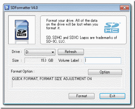
Windows and OS X users should use the SD Card Association’s formatting application; grab a copy for Windows here and OS X here. Linux users should use a format tool like Gparted for the same task. After downloading and installing the SDFormatter, fire it up with your SD card mounted. Make a quick stop in the options menu and make sure “Format Size Adjustment” is toggled on. After that, double check that you’ve selected the right piece of removable media and format it.

Once the SD card is formatted, grab a copy of the NOOBS installer. The installer comes in two versions: Offline/Network and Network Only. The Offline version is large (1.1GB) and includes both the NOOBS installer and all the available installation images; once you have this copy, you no longer need internet access to complete the installation. The Network Only version is tiny (20MB) and includes just the NOOBS installer; as you select the individual operating systems you wish to install, they are downloaded from the Raspberry Pi Foundation’s central repository.

clip_image003[1]

When the NOOBS installer has finished downloading, dump the contents of the .ZIP file onto your SD card (the contents of the full installer are shown above, those using the network installer with have an empty OS folder). After copying the required files over to the SD card, safely eject the card from your computer, place it into your powered down Raspberry Pi’s SD card slot, and power the system up.

clip_image004

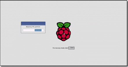
The first thing you’ll see is the screen above: the Raspberry Pi logo, a small box running some basic automated setup steps, and the instructions on the background that indicate you can switch into recovery mode by pressing up-arrow and Shift. (Although we didn’t need the recovery function because the whole process was nice and smooth, we did test it out. If anything goes wrong with your installation and you need to bring this installation wizard back up, up-arrow Shift is the way to do it.)

Once the initialization process is done, you’ll be kicked into the NOOBS wizard like so:

clip_image005[1]

The process is about as painless as it gets. As of this tutorial, there are seven operating systems available. Rasbian (the standard Debian Wheezy port), Rasbian (a boots-right-to-Scratch, lightweight and beginner-oriented programming platform popular on Raspberry Pis), Arch Linux, Pidora (a Fedora branch optimized for the Pi), OpenELEC (an XBMC branch), RaspBMC (an XBMC branch specifically tweaked for the Pi), and RISC OS (a revival of a very lightweight and snappy 1980s/1990s era Acorn-based OS optimized for the Pi).

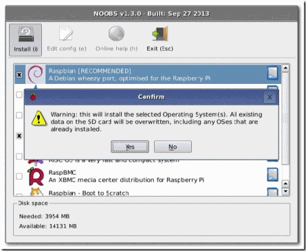
The only thing you really need to pay attention to in this step is the Disk space portion of the wizard’s display. Just installing Rasbian and Pidora sucks up around 4GB of our 16GB SD card. If you want to install all available operating systems and have room left to play, you’ll definitely want to use a 32GB card.

After making your selections, simply click the install button or press I on your keyboard:

clip_image006

We’ve already properly formatted our card, so this isn’t a concern. Press Yes to confirm.

clip_image007[1]

At this point, you’ll want to grab a cup of coffee; it takes a pretty decent chunk of time to unpack and install all the operating systems (even longer if you’re using the lighter weight on-demand network-based installer). If you have nothing else better to do than stare at it and wait, at least the NOOBS designers had the courtesy to turn the installer into a slideshow highlighting features and resources for all the operating systems you’re installing.

clip_image008

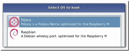
Once the process is finished, you can boot right into your installed operating systems. On each subsequent startup, you’ll be given a 10 second window to select your OS before it boots into the last-used operating system.

You will need to go through the setup process for each operating system the first time you boot it (remember, NOOBS siloes your installations, so there are no shared variables or config files).

What’s Next?

clip_image009

With the NOOBS installation out of the way and your operating systems configured, it’s time to play with your easier-than-ever-to-set-up Raspberry Pi. Here’s a list of some of our fun and helpful Raspberry Pi projects to cut your teeth on:

· Build an LED Indicator with a Raspberry Pi (for Email, Weather, or Anything)

· How to Turn a Raspberry Pi into an Always-On Usenet Machine

· How to Install NZBGet for Lightweight Usenet Downloading on Your Raspberry Pi

· How to Turn a Raspberry Pi into an Always-On BitTorrent Box

· How to Configure Your Raspberry Pi for Remote Shell, Desktop, and File Transfer

· Build a $35 Media Center with Raspbmc and Raspberry Pi, Redux

· How to Add a Printer to Your Raspberry Pi (or Other Linux Computer)

Have a Raspberry Pi project you’d love to see us tackle? Join in the conversation below and let us know.

Taken From: http://www.howtogeek.com/173101/how-to-enjoy-dead-simple-raspberry-pi-setup-with-noobs/

Arduino RF Transmitter / Receiver (MX-FS-03V / MX-05V)

How to use 315Mhz RF Transmitter and Receiver Modules with Arduino

Description: This wireless transmitter and receiver pair operate at 315Mhz. They can easily fit into a breadboard and work well with microcontrollers to create a very simple wireless data link. Since these are only transmitters, they will only work communicating data one-way, you would need two pairs (of different frequencies) to act as a transmitter/receiver pair.

Note: These modules are indiscriminate and will receive a fair amount of noise.  Both the transmitter and receiver work at common frequencies and don’t have IDs. Therefore, a method of filtering this noise and pairing transmitter and receiver will be necessary. The example code below shows such an example for basic operation. Please refer to the example code and links below for ways to accomplish a robust wireless data link.

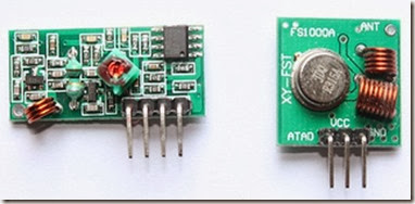
clip_image001

Module on the left: Receiver
Module on the right: Transmitter

Application environment
Remote control switch, receiver module, motorcycles, automobile anti-theft products, home security products, electric doors, shutter doors, windows, remote control socket, remote control LED, remote audio remote control electric doors, garage door remote control, remote control retractable doors, remote volume gate, pan doors, remote control door opener, door closing device control system, remote control curtains, alarm host, alarm, remote control motorcycle remote control electric cars, remote control MP3.

Receiver module parameters

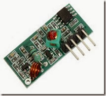
clip_image002
1. Product Model: MX-05V
2. Operating voltage: DC5V
3. Quiescent Current: 4mA
4. Receiving frequency:315Mhz
5. Receiver sensitivity:-105DB
6. Size: 30 * 14 * 7mm


Technical parameters of the transmitter module

clip_image003
1. Product Model: MX-FS-03V
2. Launch distance :20-200 meters (different voltage, different results)
3. Operating voltage :3.5-12V
4. Dimensions: 19 * 19mm
5. Operating mode: AM
6. Transfer rate: 4KB / S
7. Transmitting power: 10mW
8. Transmitting frequency: 315Mhz
9. An external antenna: 25cm ordinary multi-core or single-core line
10. Pinout from left → right: (DATA; VCC; GND)

An example:

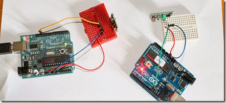
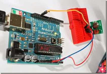
In this example, receiver and transmitter modules are connected separately to two Arduino boards. The transmitter data pin is connected to Pin 12 of Arduino and the receiver data pin is connected to Pin 11 of Arduino.

clip_image004

Data pin of transmitter module to Pin 12 of Arduino.
Data pin of receiver module to Pin 11 of Arduino.
Please note that there are two separate Arduinos for each module.

Connecting transmitter module to Arduino:

clip_image006

See all the images on flickr

Sketch:

Download library(Virtual wire)

/*
SimpleSend
This sketch transmits a short text message using the VirtualWire library
connect the Transmitter data pin to Arduino pin 12
*/

#include <VirtualWire.h>

void setup()
{
    // Initialize the IO and ISR
    vw_setup(2000); // Bits per sec
}

void loop()
{
    send("Hello there");
    delay(1000);
}

void send (char *message)
{
    vw_send((uint8_t *)message, strlen(message));
    vw_wait_tx(); // Wait until the whole message is gone
}

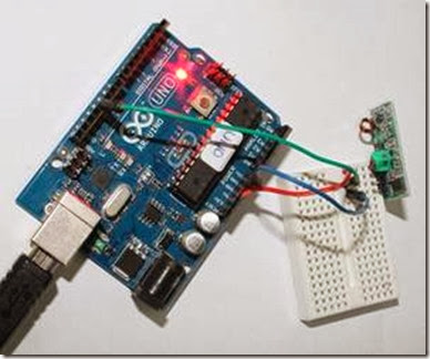
Connecting receiver module to Arduino:

clip_image008

Sketch:

/*
SimpleReceive
This sketch displays text strings received using VirtualWire
Connect the Receiver data pin to Arduino pin 11
*/

#include <VirtualWire.h>

byte message[VW_MAX_MESSAGE_LEN]; // a buffer to store the incoming messages
byte messageLength = VW_MAX_MESSAGE_LEN; // the size of the message

void setup()
{
    Serial.begin(9600);

    Serial.println("Device is ready");

    // Initialize the IO and ISR
    vw_setup(2000); // Bits per sec

    vw_rx_start(); // Start the receiver
}


void loop()
{
    if (vw_get_message(message, &messageLength)) // Non-blocking
    {
        Serial.print("Received: ");

        for (int i = 0; i < messageLength; i++)
        {
        Serial.write(message[i]);
        }

        Serial.println();
    }
}

Download library(Virtual wire)

Output:

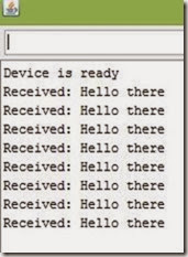
The transmitter sends a string “Hello there” and the receiver receives it and displays on serial monitor.

clip_image009

Vídeo Tutorial

Related links:

1. Virtual wire- Arduino Library

2. Buy 315Mhz receiver and transmitter modules on www.minibread.com

3. Video

4. Flickr Images

- See more at: http://www.buildcircuit.com/how-to-use-rf-module-with-arduino/#sthash.ieHxO1DS.dpuf

Taken From:

Thursday, January 16, 2014

Homemade Dropbox with Raspberry Pi and BTSync

Clone Dropbox with a Raspberry Pi and BTSync

clip_image001

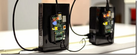
After constantly hitting my Dropbox space limit, I decided to build my own distributed backup tool. What I ended up with was an external hard drive with a dedicated Raspberry Pi that keeps in sync with my laptop over the internet using BitTorrent Sync. This new BTSync folder fully replaced my Dropbox folder, and allowed me to streamline my large media backups. I've explained every step of the build below.

Recommended Hardware

These are the items you'll need if you want to duplicate what I've built. If you're building more than 1 node, I highly recommend you buy different brand external hard drives (eg. 1 Western Digital, 1 Seagate, etc). Even different models should be sufficient. If it turns out one goes bad after a year, chances are the second won't die as well.

Install Raspbian

Grab the latest version of NOOBS (New Out of Box Software). NOOBS makes it easy to get the Raspbian OS up and running on your Raspberry Pi, along with setting some basic config options. Once you have it downloaded, copy the contents of the zip onto a freshly formatted SD card (FAT filesystem).

Once you boot up your Raspberry Pi with this SD card and install Raspbian, you'll be given a few more options. These are the settings I usually change, but you should also look around yourself to see what's available.

  • Enable SSH
  • Set the overclocking level to mild
  • Configure a unique hostname

For more detailed setup instructions, check out the installation readme included in the downloaded zip archive.

Fix the Keyboard Layout

If you're using a USB keyboard, you may notice that some of the characters aren't being entered correctly. To switch your keyboard layout from the default of English (UK) to English (US), you can follow the simple instructions after running this command.

sudo dpkg-reconfigure keyboard-configuration

Connect to WiFi

Assuming you've turned on your Raspberry Pi with the wifi dongle inserted, you can move onto configuring the wifi connection. You may want to give it a fixed IP address to make connecting to it from another machine easier. You'll find it is much quicker to SSH into the device rather than hook up a keyboard and monitor every time you want to tweak something.

Connect the External Drive

I haven't had any issues with disks formatted using ext3 or ext4, so using one of those for your external disk is recommended. You can use sudo fdisk -l to find the path of the disk (probably /dev/sda1), which you'll need for mounting. Here's how to mount it. Don't forget to change ext4 below to whatever you used.

sudo mkdir /media/external_disk

sudo mount -t ext4 /dev/sda1 /media/external_disk

Once you verify that works and you can access your files on the disk (if any), you should be able to add the disk to /etc/fstab by adding a new line like this

/dev/sda1 /media/external_disk ext4 defaults 0 0

Now when you boot your Raspberry Pi, the external drive should automatically mount.

Install BTSync

Finally you'll want to download and install BTSync. Be sure to also follow the instructions to make BTSync start on startup too, so you don't need to manually start it every time. Once it's installed and running, you should be able to configure it from any machine by pointing the browser to the Raspberry Pi's IP and port 8888 (eg http://10.0.0.12:8888). It is a good idea to go into the options and set a password for this page.

Lots of Data

The reason I started this project in the first place was because I had over 1TB of pictures and videos I wanted to keep synced across 2 hard drives in 2 different cities. While creating two nodes has done the job, I am still working on the best way to access the data without disconnecting the drive from the Raspberry Pi every time I want to add/remove something. I think my next step will be to run a samba server on each device as well, so I can treat them as network drives and access everything. FTP is also an option. What are your thoughts?

Taken From: http://reustle.io/blog/btsync-pi

Monday, January 6, 2014

Private VLANs - Trunks and SVIs (Cisco)

Private VLANs on Trunks and SVIs

By stretch | Thursday, October 28, 2010 at 1:41 a.m. UTC

This article examines the function of private VLANs across 802.1Q trunk links (not to be confused with configuring private VLAN trunk ports, which are supported only on the Catalyst 4500 and 6500 series) and how they can be mapped to SVIs for multilayer switching. For a review of private VLAN fundamentals, check outBasic Private VLAN Configuration. We'll be using the example topology below as a reference.

clip_image002

Our private VLAN configuration on S1 and S2 looks like this (if you're following along in a lab, note that the community VLANs 101 and 102 must be createdbefore being associated with the primary VLAN 100):

vlan 100

private-vlan primary

private-vlan association 101-102

vlan 101

private-vlan community

vlan 102

private-vlan community

Here are the physical interface configurations per switch for your reference:

S1

interface FastEthernet0/1

switchport private-vlan mapping 100 101-102

switchport mode private-vlan promiscuous

!

interface FastEthernet0/3

switchport private-vlan host-association 100 101

switchport mode private-vlan host

!

interface FastEthernet0/5

switchport private-vlan host-association 100 102

switchport mode private-vlan host

!

interface FastEthernet0/13

switchport trunk encapsulation dot1q

switchport mode trunk

S2

interface GigabitEthernet0/4

switchport private-vlan host-association 100 101

switchport mode private-vlan host

!

interface GigabitEthernet0/6

switchport private-vlan host-association 100 102

switchport mode private-vlan host

!

interface GigabitEthernet0/13

switchport trunk encapsulation dot1q

switchport mode trunk

Note that there is nothing special about the trunk configuration; both ends are configured as typical 802.1Q trunk interfaces.

Trunking

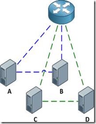
With the configurations above applied, the router is able to communicate with all hosts, and all hosts are able to communicate with the router and with the other host in their respective community private VLANs (e.g. host A can reach the router and host B, but not host C or D).

clip_image004

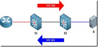
Of course, good network engineers aren't satisfied simply knowing that something works: we want to know how it works. This functionality is actually achieved by bending some rules about VLAN assignments. Traditionally, you expect return traffic originating within a VLAN to come back over the trunk tagged with that same VLAN ID. This is not always the case with private VLANs.

When the router sends a frame to one of the hosts on S2, the frame is tagged as belonging to the primary VLAN 100 when it traverses the trunk, because the router is attached to a promiscuous port. Frames originating from the hosts, however, are tagged with their appropriate secondary VLAN IDs. A frame from host B back to the router, for example, is tagged as VLAN 101 when traversing the trunk link.

clip_image006

To summarize:

· Frames originating from a promiscuous port are tagged with the primary VLAN ID

· Frames originating from a host port are tagged with the secondary (isolated or community) VLAN ID

And of course, here's a packet capture to help drive the idea home.

SVIs

What if we wanted to remove the router from our topology and do all inter-VLAN routing locally on our multilayer switch S1? No problem, we just need to create the primary VLAN SVI (switched virtual interface, also commonly referred to as a VLAN interface) and apply to it a mapping for our secondary VLANs. First we'll shut down the interface connected to the router and enable multilayer switching.

S1(config)# interface f0/1

S1(config-if)# shutdown

S1(config-if)# exit

S1(config)# ip routing

Next, we'll create the SVI for VLAN 100, assign it the IP address which was previously assigned to the router, and map our secondary VLANs.

S1(config)# interface vlan100

S1(config-if)# ip address 192.168.0.1 255.255.255.0

S1(config-if)# private-vlan mapping 101-102

S1(config-if)#

%PV-6-PV_MSG: Created a private vlan mapping, Primary 100, Secondary 101

%PV-6-PV_MSG: Created a private vlan mapping, Primary 100, Secondary 102

S1 now functions in place of the external router; all hosts can reach its routed Vlan100 interface but are still restricted to communicating with hosts in their secondary VLAN.

clip_image007

About the Author

Jeremy Stretch is a network engineer living in the Raleigh-Durham, North Carolina area. He is known for his blog and cheat sheets here at Packet Life. You can reach him by email or follow him on Twitter.

Taken From: http://packetlife.net/blog/2010/oct/28/private-vlans-trunks-and-svis/

Private VLAN – Basics (Cisco)

Basic Private VLAN Configuration

By stretch | Monday, August 30, 2010 at 12:53 a.m. UTC

Now that the community lab has been equipped with a Catalyst 3560, I have finally been able to write about private VLANs (which are supported only on Catalyst 3560 and higher switches). This article discusses the concept of private VLANs and includes a basic configuration example, with more complex configurations deferred for future articles.

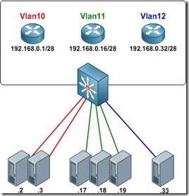
Private VLANs were developed to provide the ability to isolate end hosts at layer two. To understand the motivation behind this feature, consider a colocation environment in which the network operator must connect servers belonging to different customers to the Internet. These servers must all be able to reach their first-hop router, but for security reasons, servers belonging to one customer must not be able to communicate with servers belonging to another. An obvious design solution for these requirements is to place each customer's servers in a separate VLAN, which also requires the assignment of a separate IP subnet per customer (even if they have only one server).
clip_image002

This approach wastes both VLAN IDs and IP address space. Private VLANs were introduced as a more elegant alternative, allowing multiple devices to reside in the same IP subnet, yet remain isolated from one another at layer two.

clip_image004

A private VLAN is defined as a pairing of a primary VLAN with a secondary VLAN. Primary VLANs are the normal VLANs we all know and love. Secondary VLANs use the same VLAN ID range and are defined in the same manner as primary VLANs, but are specially designated to operate as secondary VLANs in one of two modes:

· Isolated - The end points of all ports assigned to an isolated private VLAN cannot communicate with one another, nor with host ports in any other private VLANs.

· Community - End points attached to community ports can communicate with one another, but not with ports in other private VLANs.

An access port assigned to a private VLAN operates in one of two modes:

· Host - The port inherits its behavior from the type of private VLAN it is assigned to.

· Promiscuous - The port can communicate with any other private VLAN port in the same primary VLAN.

Configuring Private VLANs

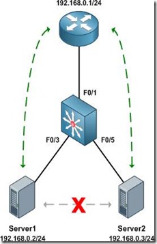
We'll configure an isolated private VLAN to allow two servers owned by different customers in the same IP subnet to communicate with their first-hop router, but not with one another.
clip_image006

Before getting started with private VLAN configuration, ensure that VTP has been set to transparent mode. There are numerous reasons for running VTP in transparent mode beyond the scope of this article, and to enable private VLANs it's explicitly required.

Switch(config)# vtp mode transparent

Setting device to VTP TRANSPARENT mode.

As with normal VLANs, private VLANs must be created before they can be used. Upon creation, we must also define a type (isolated, community, or primary) for each. We'll create our secondary VLANs first, then our primary VLAN. The secondary private VLAN is mapped under the configuration of the primary private VLAN.

Switch(config)# vlan 101

Switch(config-vlan)# private-vlan isolated

Switch(config-vlan)# vlan 100

Switch(config-vlan)# private-vlan primary

Switch(config-vlan)# private-vlan association 101

Our completed VLAN configuration looks like this:

vlan 100

private-vlan primary

private-vlan association 101

!

vlan 101

private-vlan isolated

Next, we designate our private VLAN interfaces. Our uplink port to the router will be set to promiscuous mode, with the primary VLAN mapped to the secondary VLAN.

Switch(config)# interface f0/1

Switch(config-if)# switchport mode private-vlan promiscuous

Switch(config-if)# switchport private-vlan mapping 100 101

Our two server ports will be configured in host mode:

Switch(config)# interface f0/3

Switch(config-if)# switchport mode private-vlan host

Switch(config-if)# switchport private-vlan host-association 100 101

Switch(config-if)# interface f0/5

Switch(config-if)# switchport mode private-vlan host

Switch(config-if)# switchport private-vlan host-association 100 101

At this point our private VLAN configuration is complete. We can verify private VLAN interface assignments with the command show vlan private-vlan:

Switch# show vlan private-vlan

Primary Secondary Type Ports

------- --------- ----------------- ------------------------------------------

100 101 isolated Fa0/1, Fa0/3, Fa0/5

Switch# show interface status

Port Name Status Vlan Duplex Speed Type

Fa0/1 connected 100 a-full a-100 10/100BaseTX

Fa0/2 notconnect 1 auto auto 10/100BaseTX

Fa0/3 connected 100,101 a-full a-100 10/100BaseTX

Fa0/4 notconnect 1 auto auto 10/100BaseTX

Fa0/5 connected 100,101 a-full a-100 10/100BaseTX

Fa0/6 notconnect 1 auto auto 10/100BaseTX

Fa0/7 notconnect 1 auto auto 10/100BaseTX

...

The command show interface switchport is also useful for examining private VLAN details per interface.

Finally, we can verify that the router can communicate with both servers, but the servers cannot communicate directly with one another.

Router# ping 192.168.0.2

Type escape sequence to abort.

Sending 5, 100-byte ICMP Echos to 192.168.0.2, timeout is 2 seconds:

!!!!!

Success rate is 100 percent (5/5), round-trip min/avg/max = 1/2/4 ms

Router# ping 192.168.0.3

Type escape sequence to abort.

Sending 5, 100-byte ICMP Echos to 192.168.0.3, timeout is 2 seconds:

!!!!!

Success rate is 100 percent (5/5), round-trip min/avg/max = 1/1/4 ms

Server1# ping 192.168.0.3

Type escape sequence to abort.

Sending 5, 100-byte ICMP Echos to 192.168.0.3, timeout is 2 seconds:

.....

Success rate is 0 percent (0/5)

Further Reading

· Configuring Private VLANs - Catalyst 3560 configuration guide

· RFC 5517 - Cisco Systems' Private VLANs: Scalable Security in a Multi-Client Environment

clip_image007

About the Author

Jeremy Stretch is a network engineer living in the Raleigh-Durham, North Carolina area. He is known for his blog and cheat sheets here at Packet Life. You can reach him by email or follow him on Twitter.

Taken From: http://packetlife.net/blog/2010/aug/30/basic-private-vlan-configuration/

Thursday, January 2, 2014

Universal Tablet USB Charging Adapter (DIY)

DIY Universal USB Charging Adapter (Step-By-Step w/Pics)


This DIY is based upon work done by ericlmccormick.
*DIY means DIAYOR (Do It At Your Own Risk). I'm not responsible if you break/bend/mutilate/damage/fold/crater/molest/etc. your tablet as a result of following these instructions.


If you're running Pershoot's kernel, you don't need to do this. You can enable Anycharge through the kernel. See here.

Thanks to MRBR7 for testing and confirming this also works for the GTab 7.7 6800gt.

Thanks to m_1000rr6 for testing and confirming this also works for the GTab 8.9 LTE.

Thanks to NRGZ28 for testing and confirming this also works for the Original Verizon GTab 7.


TOOLS
(Left to Right)
- Something to hold the tiny pieces together while you solder
- Wire snips
- Solder
- Pliers
- Soldering Iron

clip_image001

PARTS
(Left to Right)
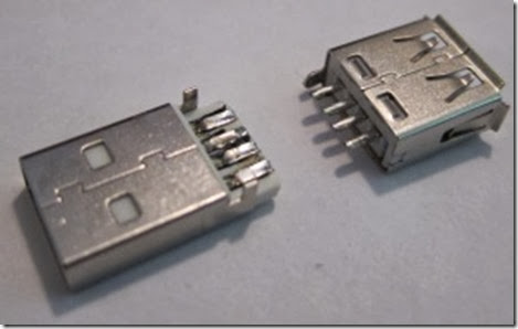
- Male USB Connector
- Female USB Connector
- One 33K Resistor
- One 10k Resistor
clip_image002
I ripped my USB connectors out of a USB extension cable.
clip_image003
Cleaned them up a bit.
clip_image004
IMPORTANT
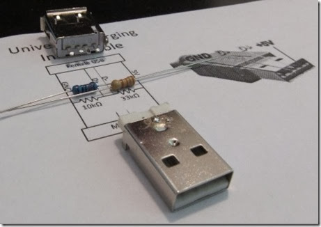
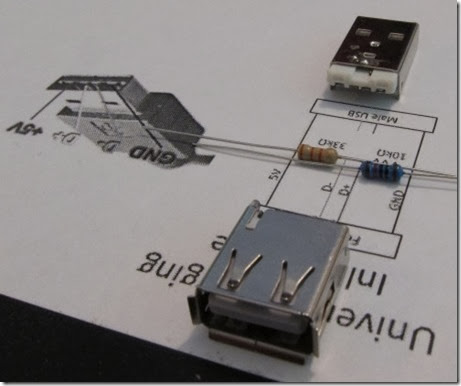
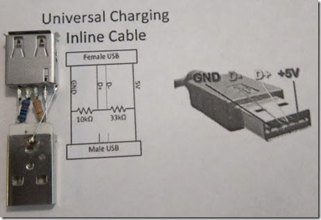
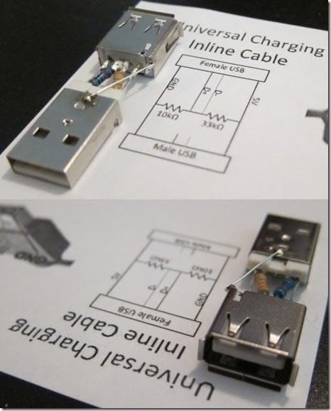
Pay constant attention to the orientation of the USB connectors to each other and which pins are GND and +5V. You could damage your Tab if you end up switching GND and +5V by mistake.You could also end up with a non-working adapter if you flip the resister locations.
clip_image005
clip_image006
clip_image007
STEP 1
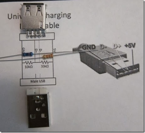
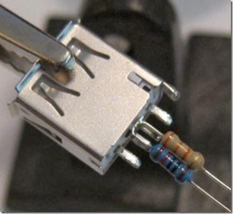
Place the resisters side by side and solder their leads together on one side. Then solder them to the D pins of the female USB connector. Make sure the 10K resistor is on the D pin closest to GND! Keep the trimmed resistor leads for use in Step 4.

clip_image008
STEP 2
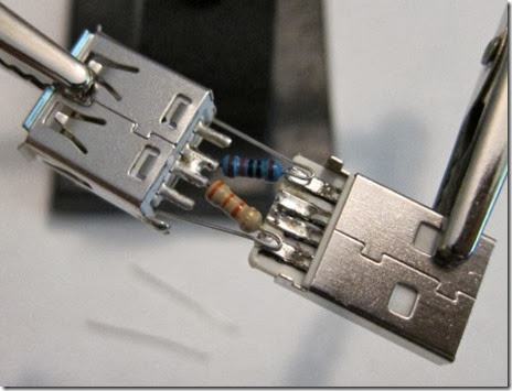
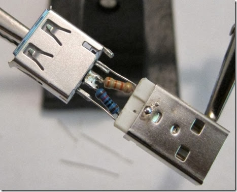
Angle the non-soldered ends of the two resistors away from each other so they line up with the GND and +5V pins of the male USB connector. Make sure the USB connectors are aligned so their respective GND and +5V pins are on the same sides! Solder.
clip_image009
STEP 3
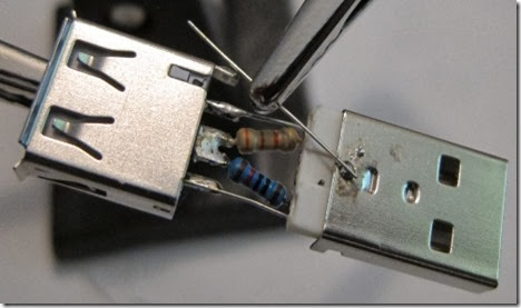
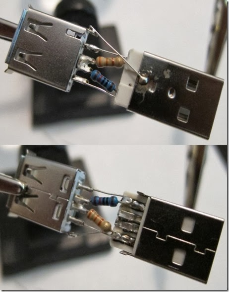
Now clip the resistor leads that were bent back towards the female USB connector and solder them to its GND and +5V pins. Double check that the USB connectors are aligned so their respective GND and +5V pins are on the same sides! BE PARANOID.
clip_image010
STEP 4
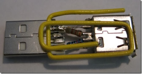
Use the trimmed resistor lead you kept from Step 1 to solder the chassis of the USB connectors together.
clip_image011
STEP 5
Take 5 minutes to admire your handiwork.
clip_image012
STEP 6 (IMPORTANT - DO NOT SKIP)
Take 10 minutes to check the following
(1) USB connectors are lined up correctly. GND & +5V are not crossed.
(2) 10K resistor comes from GND and 33K resistor comes from +5V. Adapter won't work otherwise.
(3) There are not short circuits / crossed / touching wires. Many bad things could happen.
clip_image013
clip_image014
STEP 7 (TEST)
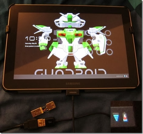
Without adapter. @$%#!
clip_image015
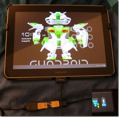
With adapter. Success!
clip_image016
NEVER CONNECT YOUR TAB TO A USB PORT THAT SUPPLIES MORE THAN 2A - BE PARANOID.
STEP 8
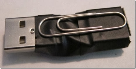
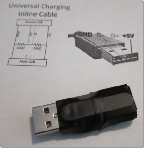
Reinforcing and packaging (paperclips & electrical tape).
clip_image017
clip_image018
clip_image019
STEP 9
Thank me (hit that button over there clip_image021
Hope you found this post useful and informative.

Taken From: http://forum.xda-developers.com/showthread.php?t=1675042